
|
|
|


|
|

|
|
|
|
|
|
|
|
|
|
|
Finite Element Modelling of stresses, strains and deflections in perforated panels subjected to lateral loads.
|
|
|
|
|
Structures and structural components with plates and shells are common design parts encountred in mechanical, aeronautical and civil engineering. Mathematical methods comprising the basis for design and analysis of solid plates and
shells are well established. However, structural designs often
incorporate perforations, for a variety of reasons:
to reduce the materials weight and consumption,
to reduce the loads,
provide openings to allow ventilation and light, etc.
Accurate mathematical analysis of those perforations is required for determining the correct deflections, bending and twisting moments, shear forces, and stresses. When a plate is perforated with a large number of holes (of circular or some other shape) , assembled in a specific pattern, its structural analysis under loading cannot be performed using the same approach as for solid plates, because stress distributions in the vicinity of the openings would be drastically different from those arising in continuous bodies.
Different industries have a variety of engineering applications involving perforated plates and panels. One of the examples is the heat exchanger industry, which is focusing on tube sheet behaviour. Even more common examples include broad use of perforated panels in civil engineering; the panels can be of different shapes, sized and perforation patterns.
PERFO-PLATE 1.0 is a stand-alone software application for Finite Element analysis of stresses and deflections in laterally loaded 2D panels with complex perforation patterns. It allows the user to
specify the perforated plate dimensions,
choose a perforation pattern from a list of supported patterns,
specify perforations' size,
apply boundary conditions at the panel edges, and
set the elastic material parameters as well as the value of lateral load.
PERFO-PLATE 1.0 software
automatically generates all the input data files,
performs meshing of the perforated plate surface,
performs Finite Element Analysis of the plate structural response to loading, and
outputs the computational results, namely nodal displacements and the stress resultant moments and forces.
PERFO-PLATE 1.0 performs 2D and 3D rendering of the input data describing the perforated panel,
namely
the finite element mesh,
the lateral load and
the nodal constrains.
PERFO-PLATE 1.0 also performs 2D and 3D rendering of computational results, namely
the nodal deflections (the distorted finite element mesh),
the contour lines of bending and twisting moments,
the contour lines of transversal shear forces, and
the reaction forces and moments computed at constrained nodes.
PERFO-PLATE 1.0 is offered either with complete source codes
written in standard C/C++, or as a standalone executable. It is available without
any royalties or additional fees.
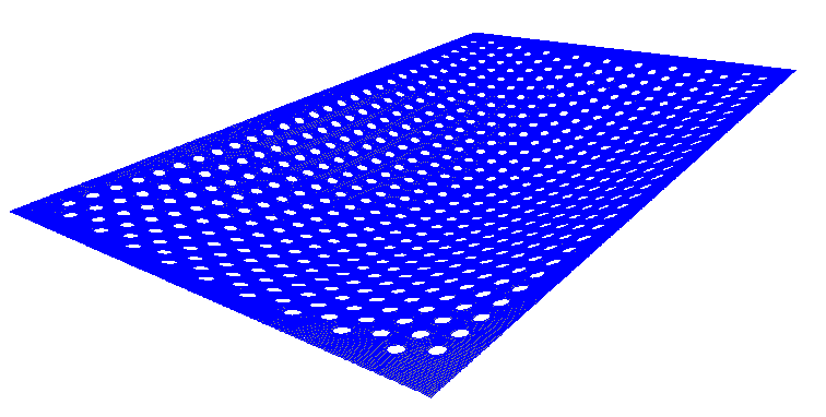
As an example, consider deformation of a 2x3 meters perforated aluminium panel with staggered pattern.
The panel is simply supported on all four edges and is subjected to lateral wind load.
The parameters of the model are as follows:
the Young's modulus E = 71 GPa
Poisson ratio v = 0.34
material thickness h = 3 mm
wind pressure p = 375 Pa (which corresponds to the wind speed of 25 meters per second)
Presented below are:
the panel deformed state (rotated from the normally vertical position in order to simplify the visual examination),
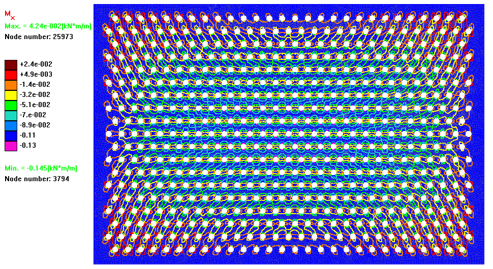
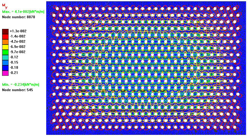
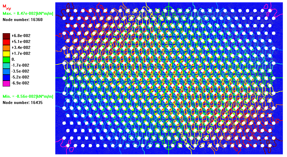
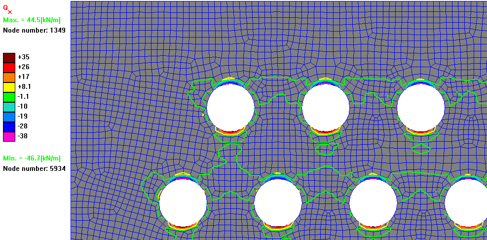
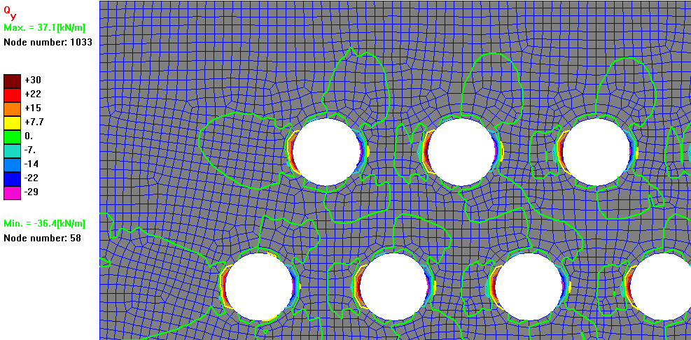
distribution of bending moments Mx, My and the twisting moments Mxy over the whole panel, and
distribution of shear forces Qx and Qy in the top left-hand corner of the panel.
|
|
|
|
|
|
|
|
|
|
|
|
|
|
|
|
|
|
|
|
|
|
|
|
|
|
|
|
|
|
|
|
|
|
|
|
|
Several important conclusions can be made after careful examination of the obtained results presented above.
First, it can be seen that the maximum (by absolute value) bending moments Mx
and My are located around the holes in the central part
of the panel (the corresponding contours are coloured purple; the negative sign means that the fibres on the top surface
experience compression, not tension, which was expected since the wind load is vertically applied to the top surface).
It is easy to evaluate the maximum tensile stresses in the bottom fibres:
|
|
|
|
|

|
|
|
It can be seen that both values exceed, for example,
the tensile yield strength of popular Alcoa aluminium alloy 5052-O, which is equal 89.6 MPa .
Such observation justifies the necessity of the performed analysis and
demonstrates that the panel, in order to withstand even moderate wind loads without destruction or significant plastic deformation,
must be made of more stress-resistant material or have its thickness increased.
Another observation is related to the twisting moment Mxy: it can be seen that the moments with
maximum values are primarily located in the vicinities of the four corners of the panel.
Finally, it can be noticed that the maximum shear forces Qx and Qy arise around the holes located near the corners of the panel,
and gradients of those forces are very large (the countours corresponding to different values of the shear force
are located very close to each other).
New ! In the year 2016 our company undertook substantial research in order
to evaluate how the more complex perforation patterns (slotted, hexagonal, etc.) and applied
boundary conditions influence the distribution of the bending and twisting moments,
and shear forces. The most dangerous locations, where the von Mises stresses
reach their maximum values, have been identified. A report, also containing to the obtained results,
can be found here .
PERFO-PLATE numerical results are presented in a number of files using the standard (ASCII) text format, and include
displacements and angles of rotation at the mesh nodes
bending moments, twisting moment and lateral and shear forces computed at the finite elements' center points
reactions at the constrained nodes.
Since PERFO-PLATE can be provided with complete source codes, the numerical output can be readily extended and modified to suit
the user's needs.
PERFO-PLATE is a customized modification of our general plate analysis product QUAD-PLATE offered in 2D and 3D implementations. All implementations are based on
the Mindlin theory of plates.
To illustrate the capabilities of QUAD-PLATE 2D, consider structural analysis of bending of
perforated panel under wind loading.
To illustrate the capabilities of QUAD-PLATE 3D, consider structural analysis of Mobile
Offshore Drilling Unit.
To illustrate the accuracy of QUAD-PLATE, consider the problem of bending of thin plate
under the action of uniform load for which the analytical solution is known.
|
|
|
|
|
PERFO-PLATE is available with complete source codes
and the full commercial lisence allowing easy incorporation into your own
applications.
All codes are fully commented, allowing easy modification at user's discretion.
PERFO-PLATE is available on no-royalties and
no-annual-renewals basis: there is a one-off price for an
unlimited commercial lisence.
PERFO-PLATE standard distribution kit includes:
- fully-commented source codes of the program in C and C++, and
- a graphical application that allows the user to visualize input and output data for each particular
example created by the user.
PERFO-PLATE has been completely developed by our company and contains
no third party code.
To learn more about the full range of our products please follow this
link.
We invite you to contact us, preferably by e-mail on
comecauinfo@gmail.com
Alternatively, please send us SMS message on +61-411-278-528 or call us on the same number.
|
|
|
|
|
|
|
|
|
|
|
|
|
|